Maker / Project
Rebuilding the garage doors
A clean white finish, an insulated core and a timber frame that can be repaired. A new life for the existing garage doors.
This build uses 2×4 framing, 15/32 in exterior plywood, a thinner 1/5 in inside lining and applied trim. Explore every layer, then follow the workshop sequence.
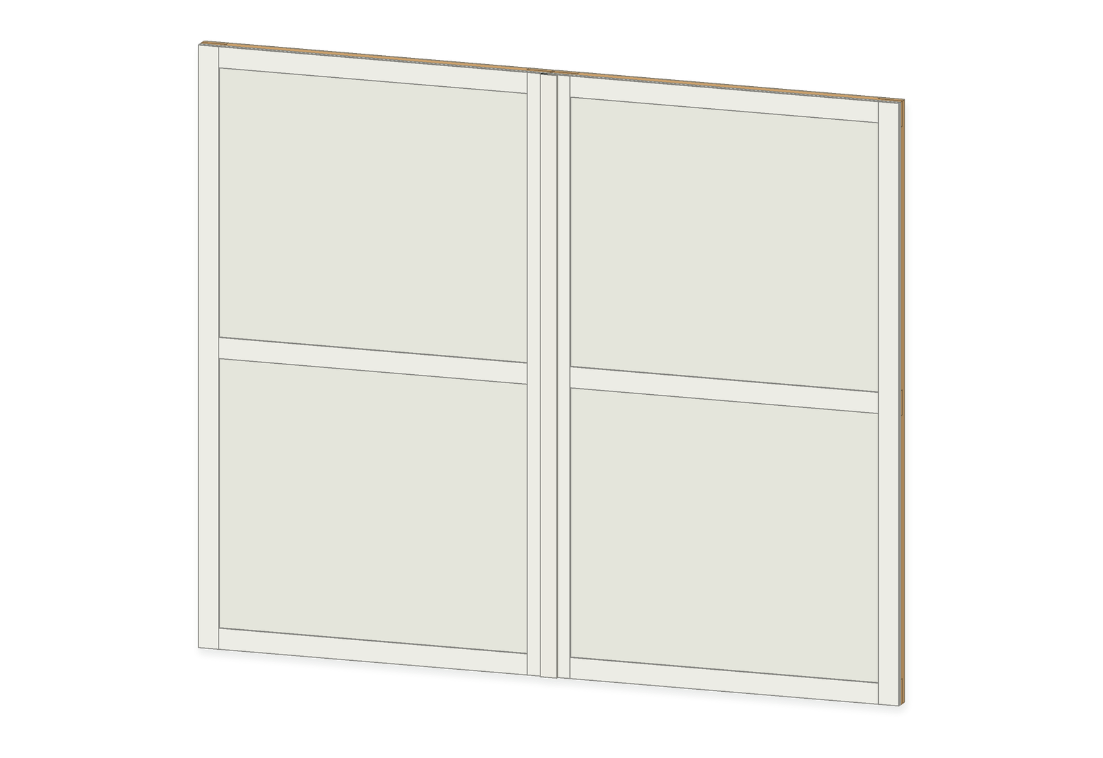
- Leaf cut outline
- 127.565 × 213.865 cm
- Frame stock
- 2×4 timber
- Operation
- Outward · right first
- Workshop manual
- 27 illustrated pages
Explore the assembly
Rotate the doors, separate the layers, inspect individual parts or switch to the frame joint and build sequence. The opening control demonstrates why the right door moves first.
Drag to rotate. Use Camera and Part for keyboard inspection. Part sizes use inches; cut instructions use cm.
Open viewerMaterials and equipment
Retain sound existing timber and braces. Cut replacement frame members only where the inspection calls for them. The table uses the stock and hardware names to look for when buying.
| Material | Purchased stock / hardware | Use for both doors |
|---|---|---|
| Frame timber | 2×4; actual 1½ × 3½ in | Up to 4 uprights + 6 rails for both leaves |
| Exterior plywood | 15/32 in; main sheets 4 ft wide | 2 main panels + 2 matching infill strips |
| Interior plywood | 1/5 in; main sheets 4 ft wide | 2 main panels + 2 matching infill strips |
| Insulation | 1½ in rigid foam | 4 fitted inserts before hardware-blocking changes |
| Exterior trim and cover | Model thickness approximately 0.236 in | 4 vertical trim + 6 horizontal trim + 1 center cover |
| Center spacer | Example thickness approximately 0.118 in | 1 fitted strip |
| Center gasket | Model profile about 0.866 in wide and 0.118 in compressed | 1 fitted run |
| Decorative-trim screws | Example: GRK FIN/Trim #8 × 1½ in; T10 drive | 76 proposed trim fixings |
| Center-cover screws | Example: GRK FIN/Trim #8 × 2 in; T10 drive | 10 proposed additional cover fixings |
The modeled trim thickness is 0.236 in and the example spacer is 0.118 in. Measure your actual strips before calculating screw reach or setting the center seal. The 1/5 in inside lining is the current reference; select the exact foam and confirm its required protective covering.
- Choose plywood with an exposure classification suitable for the finished exterior application. Thickness alone does not identify the grade.
- Use an adhesive approved for the selected foam, facing and wood. Allow for its adhesive bed so the inside lining remains flat.
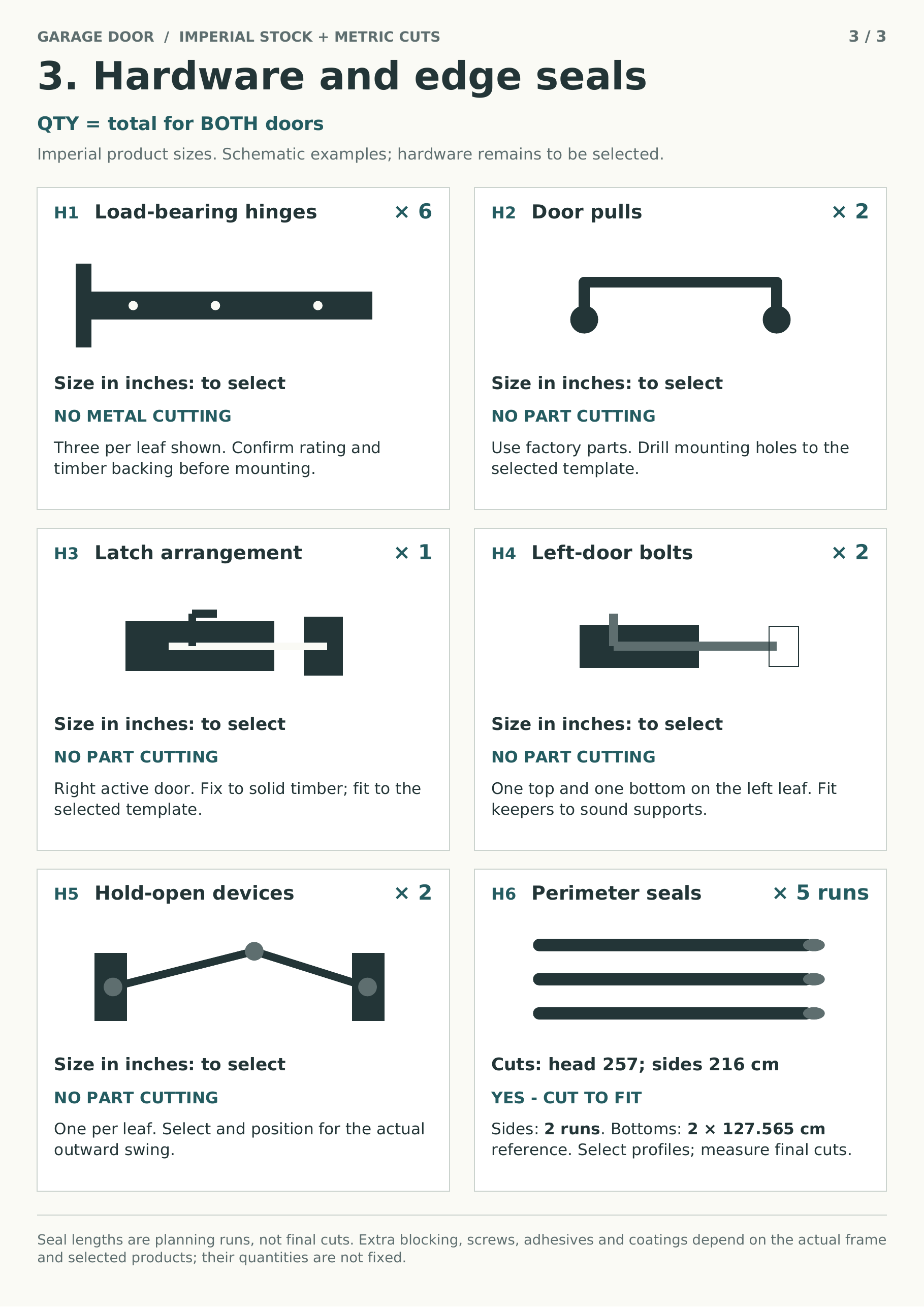
- Planning hardware: 6 hinges, 2 pulls, 1 active latch, 2 bolts for the left leaf and 2 hold-open devices. Confirm their capacity and mounting details for the completed leaves.
- Tools: tape, square, straightedge, marking knife, guided saw, handsaw, sharp chisel, clamps and flat supports; drill/driver with an adjustable clutch, a T10 driver and imperial bits selected for the actual screw and wood.
Every part and its cut
Quantities below cover both doors. All cut values in this table are centimeters; stock sizes stay imperial. The frame quantities apply only if those members need replacing. Use the exact CSV when transferring the model values.
| Part | Qty | Stock · imperial | Cut · cm | Cut needed? |
|---|---|---|---|---|
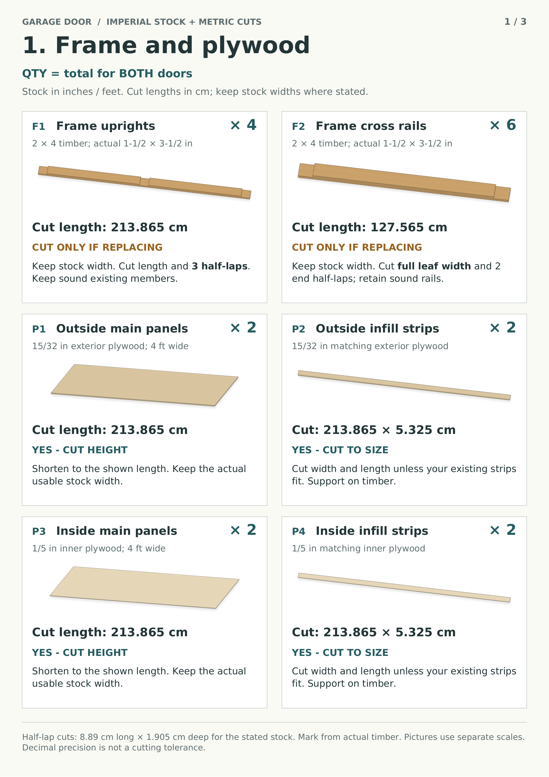
| F1 · Vertical frame members | 4 | 2 x 4 timber; actual 1-1/2 x 3-1/2 in | 213.865 long | Replacement only |
| F2 · Horizontal frame members | 6 | 2 x 4 timber; actual 1-1/2 x 3-1/2 in | 127.565 long | Replacement only |
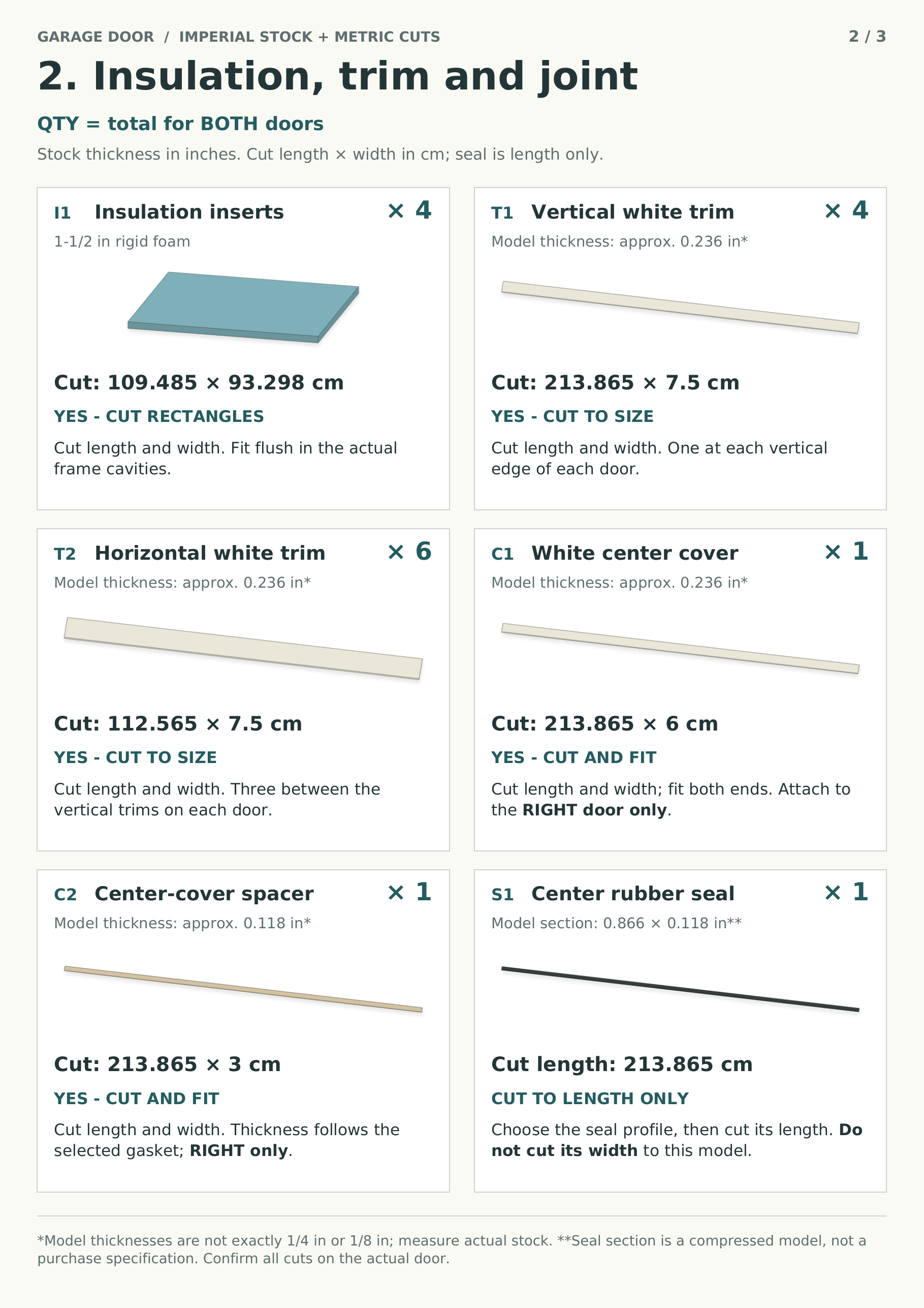
| I1 · Insulation inserts | 4 | 1-1/2 in rigid foam | 109.485 × 93.2975 | Cut / fit |
| P1 · Exterior plywood: main panels | 2 | 15/32 in exterior plywood; 4 ft wide | 213.865 × 121.92 | Cut / fit |
| P2 · Exterior plywood: extra strips | 2 | 15/32 in matching exterior plywood | 213.865 × 5.325 | Cut / fit |
| P3 · Interior plywood: main panels | 2 | 1/5 in inner plywood; 4 ft wide | 213.865 × 121.92 | Cut / fit |
| P4 · Interior plywood: extra strips | 2 | 1/5 in matching inner plywood | 213.865 × 5.325 | Cut / fit |
| T1 · Vertical white trim | 4 | Model thickness approximately 0.236 in | 213.865 × 7.5 | Cut / fit |
| T2 · Horizontal white trim | 6 | Model thickness approximately 0.236 in | 112.565 × 7.5 | Cut / fit |
| C1 · White center cover | 1 | Model thickness approximately 0.236 in | 213.865 × 6 | Cut / fit |
| C2 · Center cover spacer | 1 | Model thickness approximately 0.118 in; select after gasket | 213.865 × 3 | Cut / fit |
| S1 · Center weather gasket | 1 | Model compressed section approximately 0.866 x 0.118 in; not a purchase specification | 213.865 long | Length only; fit on site |
P1 and P3 keep the reference sheet width. Measure the usable sheet before fitting P2 and P4: 127.565 − 121.92 − 0.32 = 5.325 cm. The 0.32 cm seam is a movement allowance; it is separate from saw kerf. Re-measure foam cavities after hardware backing is installed.
Frame + plywood
Insulation + trim
Hardware + seals
Build, one step at a time
Work on a supported leaf and keep its reference faces marked. Close the skins only after the frame repairs, hardware backing and access-dependent fittings are complete.
Open a step for its instructions and drawing.
01Open and inspect the existing leafWork on one supported leaf at a time. Keep sound framing and existing braces.
- Support the leaf securely before releasing its hinges. Mark LEFT or RIGHT, TOP, OUTSIDE and the hinge edge. Photograph the hardware positions and record the existing gaps.
- Lower the leaf onto flat, padded supports. Remove the skins carefully to preserve sound framing, joints and braces.
- Inspect for decay, splits, loose joints and twist. Mark the actual repairs before ordering or cutting replacement timber.
Check The original frame layout and hardware positions are recorded. The leaf is flat and every proposed repair is identified.
Manual · page 6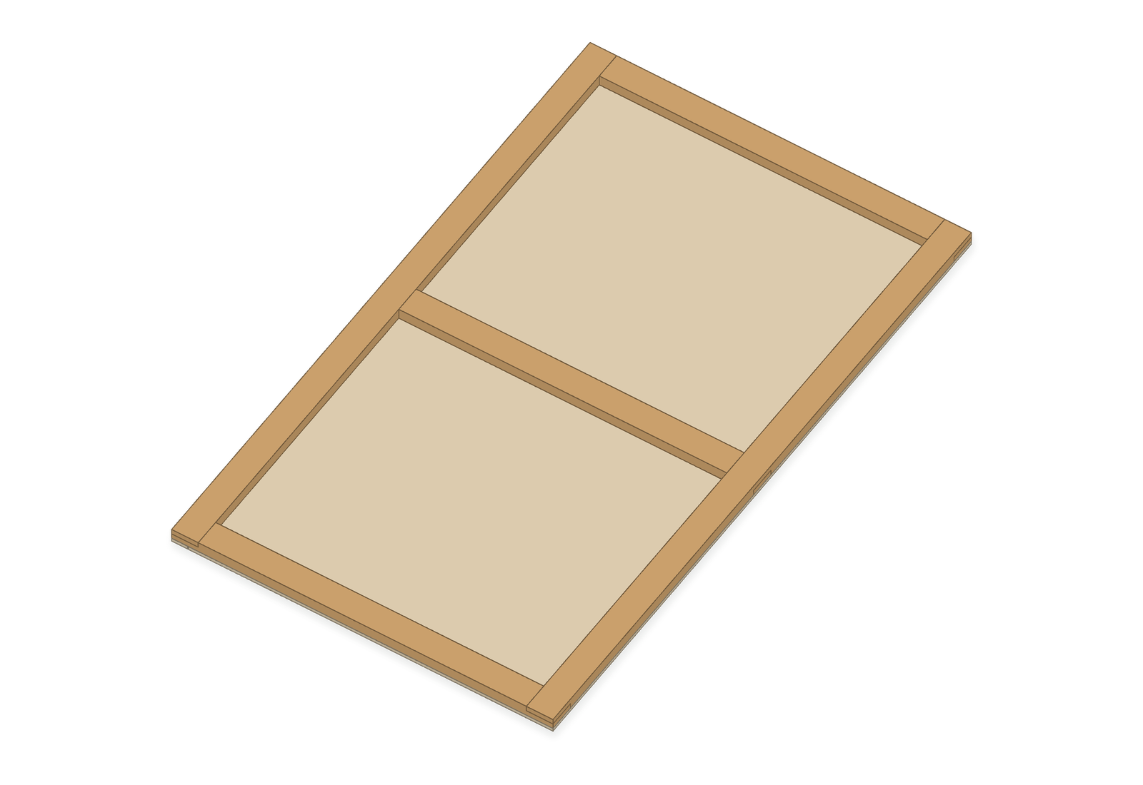
02Repair and square the frameThe reference leaf has two uprights and three full-width rails. The half-lap cuts apply to replacement members.
Cuts and layout · cm
- F1: 213.865 cm long; four for the pair.
- F2: 127.565 cm long; six for the pair.
- Half-lap cut depth: 1.905 cm for actual 1½ in stock.
- Use 2×4 timber laid flat: actual 3½ in face and 1½ in depth. Crosscut the replacement blanks square; retain the stock width.
- Remove the outside half of each upright at the three rail positions, and the inside half of each rail at its two ends. Use the cut map below and mark from one squared reference end.
- Trial-fit the joints. Both faces must finish flush and the shoulders must touch. Clamp the leaf flat at the provisional 127.565 × 213.865 cm outline; the two reference diagonals are 249.020 cm.
- Complete the selected joint connection and racking reinforcement for the actual timber and door load before adding skins.
Check The frame is square and flat, with its joint fastenings and resistance to sag resolved. The full rail length includes the end overlaps.
Manual · pages 7, 8, 25, 26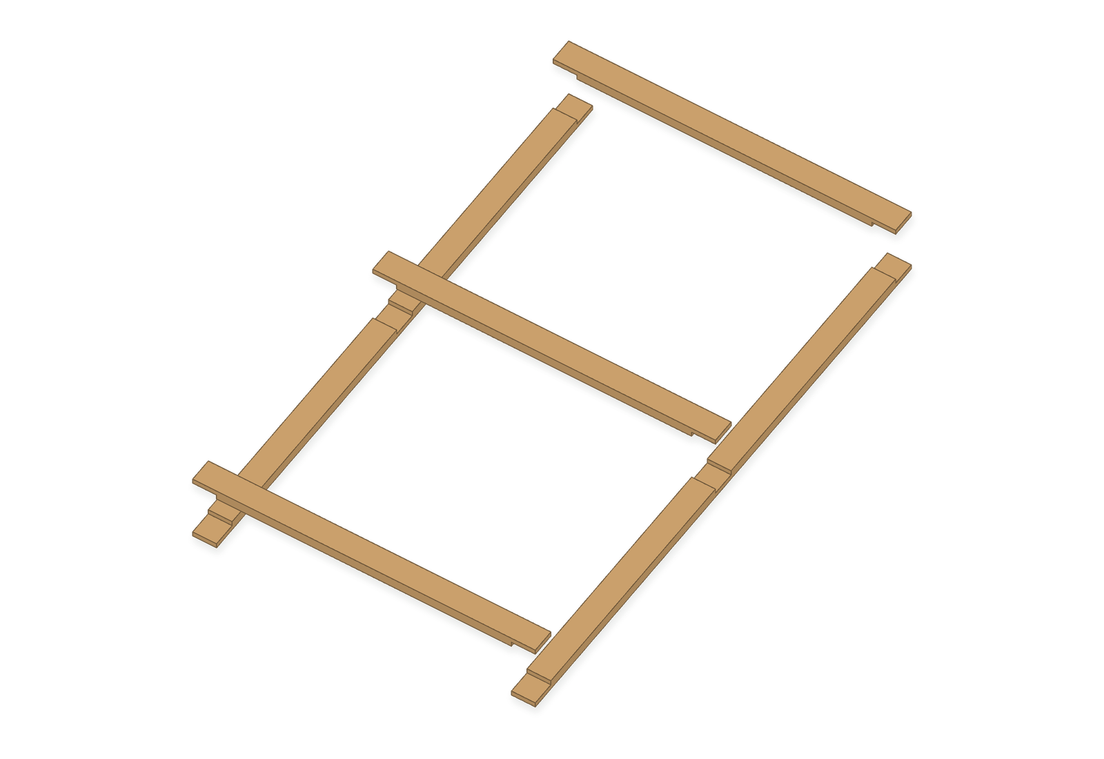
03Prepare the hardware backingSelect the real hinges, latch and bolts before closing the frame.
- Place the actual hardware templates on the frame and mark the mounting holes, clearances and keeper positions.
- Align loaded fixings with sound rails or uprights. Where needed, add securely connected full-depth backing to the actual hole pattern within the 1½ in core.
- Install access-dependent fasteners, nuts and backing plates now. Update the foam cuts and final weight allowance for the added pieces.
Check Every loaded fixing reaches sound door framing and a suitable structural jamb. Foam and thin plywood are not hinge backing.
Manual · page 904Attach the exterior plywoodThe matching narrow infill strip sits at the meeting edge of each door.
Cuts and layout · cm
- P1: cut height to 213.865 cm; reference width 121.92 cm.
- P2: 213.865 × 5.325 cm.
- Supported movement seam: 0.32 cm.
- Dry-fit the 15/32 in main panel and matching strip on the flat frame. Mirror the pair so both narrow strips are at the center.
- Hold the 0.32 cm reference joint with removable spacers. Both plywood edges and the whole narrow strip must bear on the meeting upright.
- Mark the timber lines on the face and fix each plywood piece independently with the selected skin-to-frame connection. Remove the spacers once the strip is held.
- Keep the seam free of rigid filler or a continuous rigid glue bridge. The decorative trim will cover it later.
Check Recalculate strip width from the actual leaf width, usable main-panel width and selected joint gap. The reference calculation is 127.565 − 121.92 − 0.32 = 5.325 cm.
Manual · pages 10, 11, 21, 22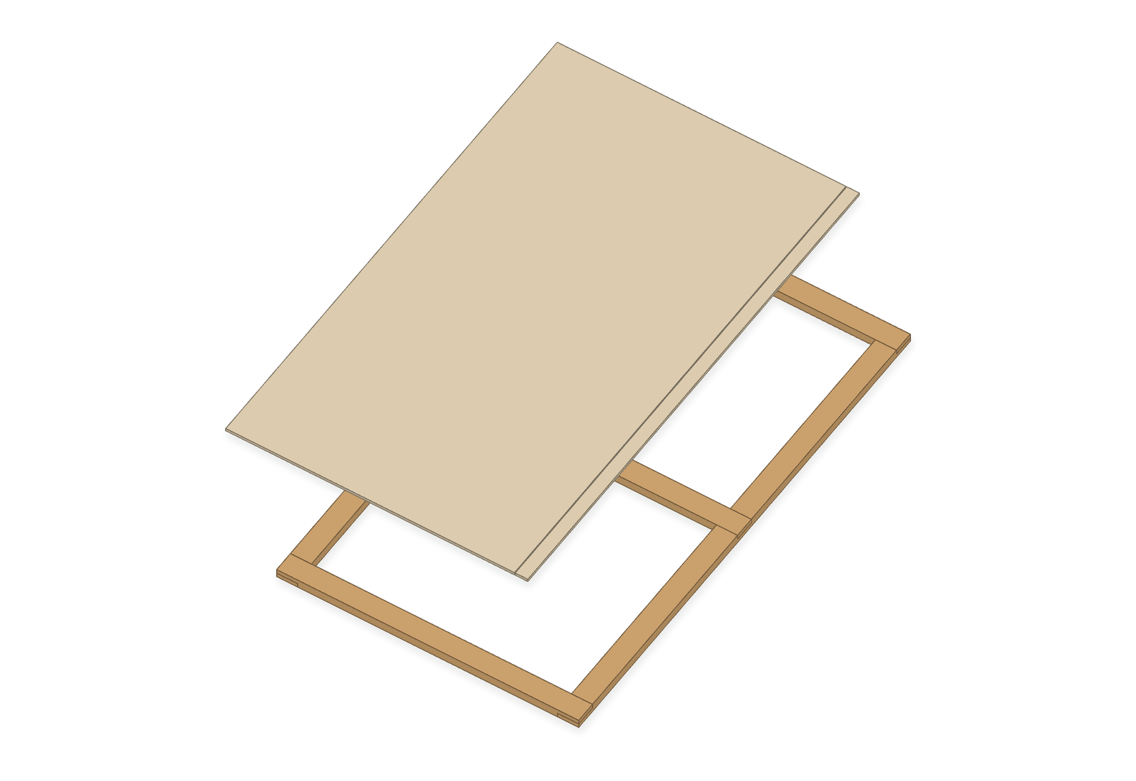
05Fit the insulationMeasure the cavities after repairs and hardware backing. Keep the inserts flush with the timber.
Cuts and layout · cm
- I1: 109.485 × 93.2975 cm; four inserts for the pair, before adjustments for blocking.
- Turn the leaf only when the exterior-skin bonding system permits handling. Set its outside face on padded, flat supports.
- Cut and trial-fit 1½ in rigid foam to the actual cavities. Allow room for adhesive bedding so the foam cannot bow the inside lining.
- Use an adhesive approved for the exact foam, facing and substrate. Follow its application, retention and full-cure instructions.
Check A straightedge across the timber does not rock on proud foam. Confirm the selected insulation’s covering requirements before closing the inside.
Manual · page 12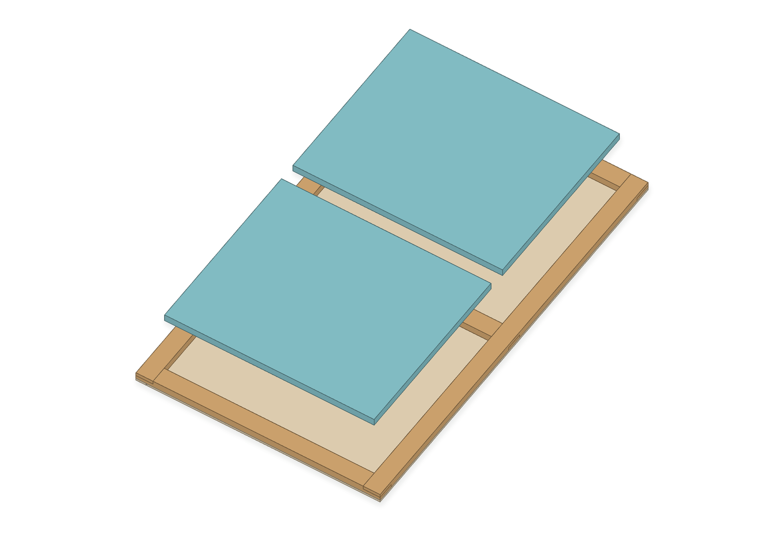
06Close the inside faceThe current reference uses the user-stated 1/5 in plywood lining.
Cuts and layout · cm
- P3: cut height to 213.865 cm; reference width 121.92 cm.
- P4: 213.865 × 5.325 cm.
- Dry-fit the main lining and matching strip with the same supported seam at the meeting upright.
- Transfer all timber and backing lines to the lining. Fix into wood using the selected lining connection, seating the heads without crushing or pulling through the veneer.
- Keep the leaf supported flat for the required cure. Check its diagonals, face flatness, exposed edges and remaining hardware access.
Check The thin lining is not structural hinge backing. Its suitability as a protective covering depends on the selected insulation product.
Manual · pages 13, 22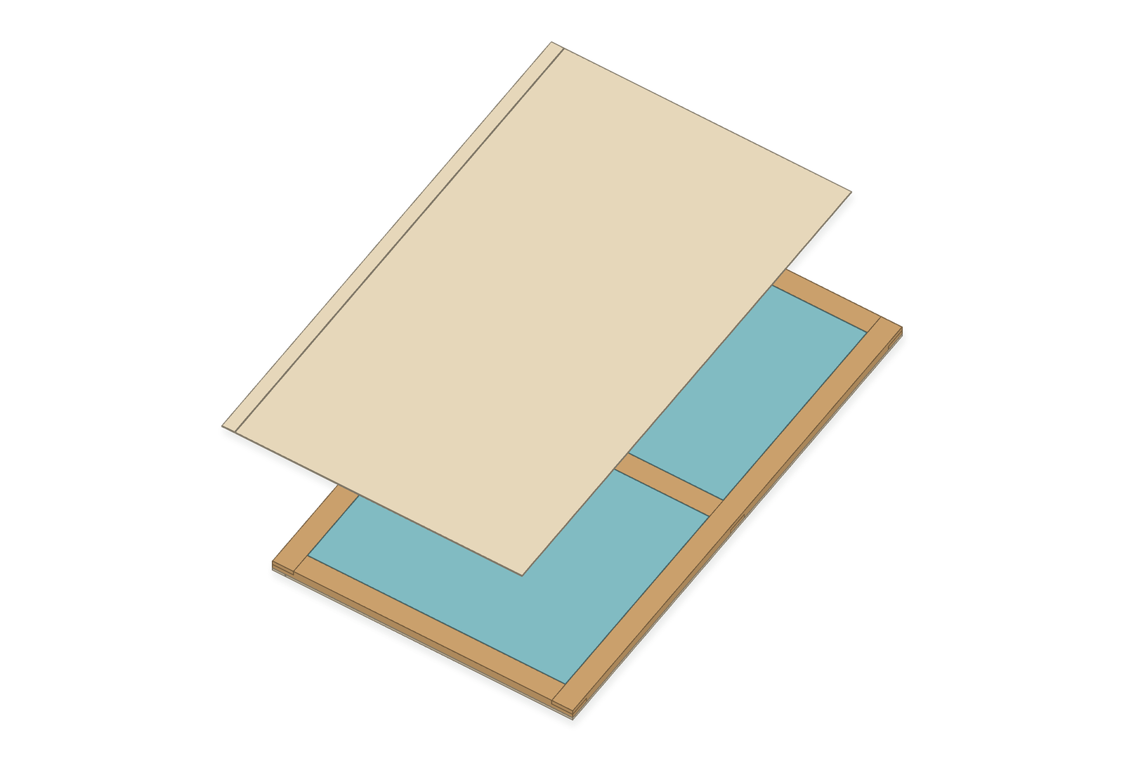
07Fit the decorative trimTwo full-height vertical pieces frame three horizontal pieces on each outside face.
Cuts and layout · cm
- T1: 213.865 × 7.5 cm; four total.
- T2: 112.565 × 7.5 cm; six total.
- Horizontal trim lower edges: 0, 103.1825 and 206.365 cm above each leaf bottom.
- Dry-fit the vertical T1 pieces first. Fit T2 between them with square 90° ends. Transfer one common horizontal reference across the closed pair.
- Mark the hidden timber and clamp the trim. The proposed screw row follows the strip centerline, 3.75 cm from its long edge.
- For this decorative-trim proposal, use 10 screws per T1 and 6 per T2: 76 for both doors. Place the first and last 5 cm from the ends and space the rest evenly.
- Test the screw head and drilling on matching offcuts. Drive slowly to flush. At the plywood seam, keep trim fixings on the narrow-strip side and stagger them to miss the earlier skin screws.
Check Example hardware: exterior-compatible GRK FIN/Trim #8 × 1½ in, T10 drive. The proposed count retains decorative trim; it is not a frame, skin or hinge fastening schedule.
Manual · pages 14, 21, 22, 23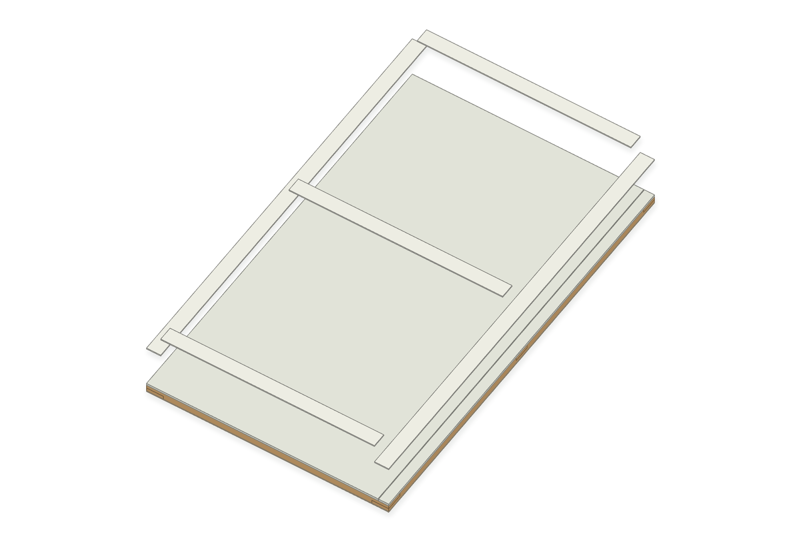
08Seal and finish the woodComplete the exterior finish before exposure, including the edges that will be hard to reach after hanging.
- Sand, remove dust and ease sharp exposed edges enough for coating coverage without changing joint bearing or fit.
- Follow the selected exterior finish system on both faces, all four door edges, trim ends and cut plywood edges. Preserve any areas that must remain bare for a later bond.
- Allow the stated cure. Reseal new cuts and drilled preparations after later fitting and hardware work.
Check Inspect the top and bottom edges while the leaf is still on supports. Use the coating manufacturer’s coverage and cure instructions.
Manual · page 15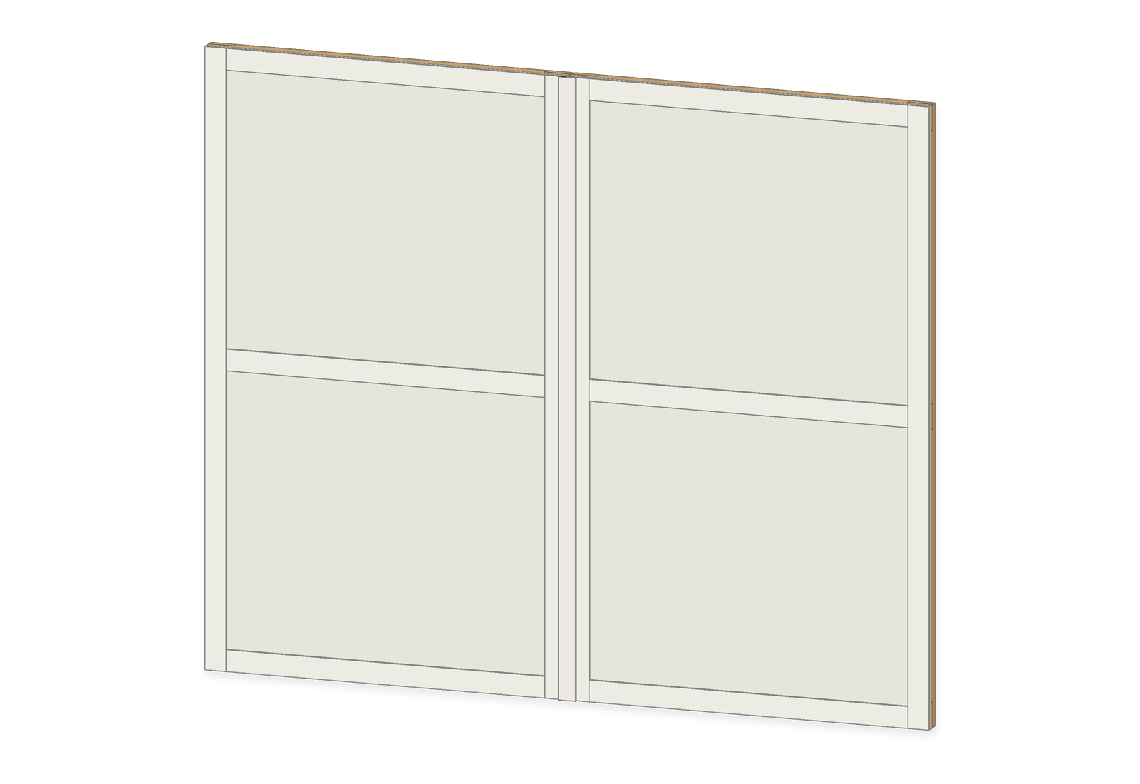
09Weigh, check the hinges and hangConfirm the complete leaf load and hardware before a trial hang.
Cuts and layout · cm
- Starting allowances: top and sides 0.635 cm; center 0.6 cm; bottom 1.5 cm. Fit to actual hinges, seals and floor slope.
- Weigh each leaf in pounds with all fitted parts, and include the measured weight of anything still to be added. Confirm the hinges, joints, fasteners and jamb for the actual width, weight and exterior exposure.
- With a helper and secure support equipment, position the left leaf and then the right. Keep the leaves level with each other and the hinge axes aligned.
- Use the actual hinge template and specified fasteners. Keep the doors supported while checking the complete outward swing over the highest floor point.
Check Three hinges per leaf are a planning count, not a capacity rating. The 3D model’s ideal hinge axes are not drilling templates.
Manual · pages 16, 2010Fit the center cover and gasketThe cover, spacer and gasket move with the active right door.
Cuts and layout · cm
- C1: 213.865 × 6 cm before final end fitting.
- C2: 213.865 × 3 cm before final end fitting.
- S1: cut the selected seal to the fitted length.
- Cover width: 2.4 cm free left overlap + 0.6 cm center gap + 3 cm right support.
- Screw row: 1.5 cm inside the right meeting edge, or 4.5 cm from the cover’s left edge.
- Close and secure the left leaf, then align the right. Select the actual gasket before setting the spacer thickness.
- Fit the cover and spacer ends to the head and bottom weather details. Fasten into the right meeting timber only; stagger the holes to miss earlier fixings.
- Fit the gasket under the free overlap. An example cover fixing is exterior-compatible GRK FIN/Trim #8 × 2 in. The proposal uses 10 additional screws, about 5 cm from fitted ends and evenly spaced.
- Keep the cover removable for gasket servicing. Open the right door first and check that the overlap releases freely from the left.
Check No screw or rigid glue joint crosses into the left leaf. Fit pulls and latches to suitable framing rather than the thin cover.
Manual · pages 17, 24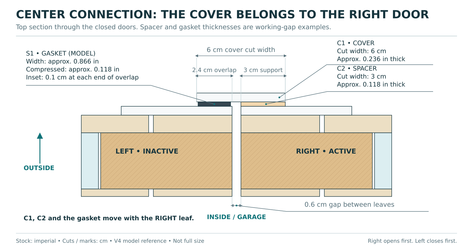
11Fit the latch, bolts and sealsUse the selected hardware templates and fit each weatherseal to its actual installed gap.
Cuts and layout · cm
- Head seal: 257 cm reference.
- Side seals: two at 216 cm reference.
- Bottom seals: two at 127.565 cm reference.
- Measure final fitted lengths; the head, sides and bottom may need different seal profiles.
- Fit the top and bottom bolts to the left door, the active latch to the right, and a pull and hold-open device to each door. Secure loaded hardware into suitable backing.
- Fit the head and jamb seals to sound stops. Fit the bottom seals to the floor or threshold without using them to support the doors.
- Connect the center gasket to the head and bottom weather details. Check continuous contact, free movement and edges that shed water.
Check The latch should close without lifting a leaf. Seals must not bind or trap water along the lower edge.
Manual · page 1812Test the opening sequenceRight opens first. Left closes and bolts first.
- To open: unlatch and open the right door, release the left bolts, then open the left. Secure both with their hold-open devices.
- To close: close the left door and secure its bolts, then close and latch the right door over the center gasket.
- Check the full swing, hinge anchors, latch, even gasket contact and finished edges. Support and adjust any door that rubs, drops or loads the latch.
Check Record actual sizes, leaf weights, hinge models and fastener specifications. Recheck after initial use and seasonal weather changes.
Manual · pages 19, 20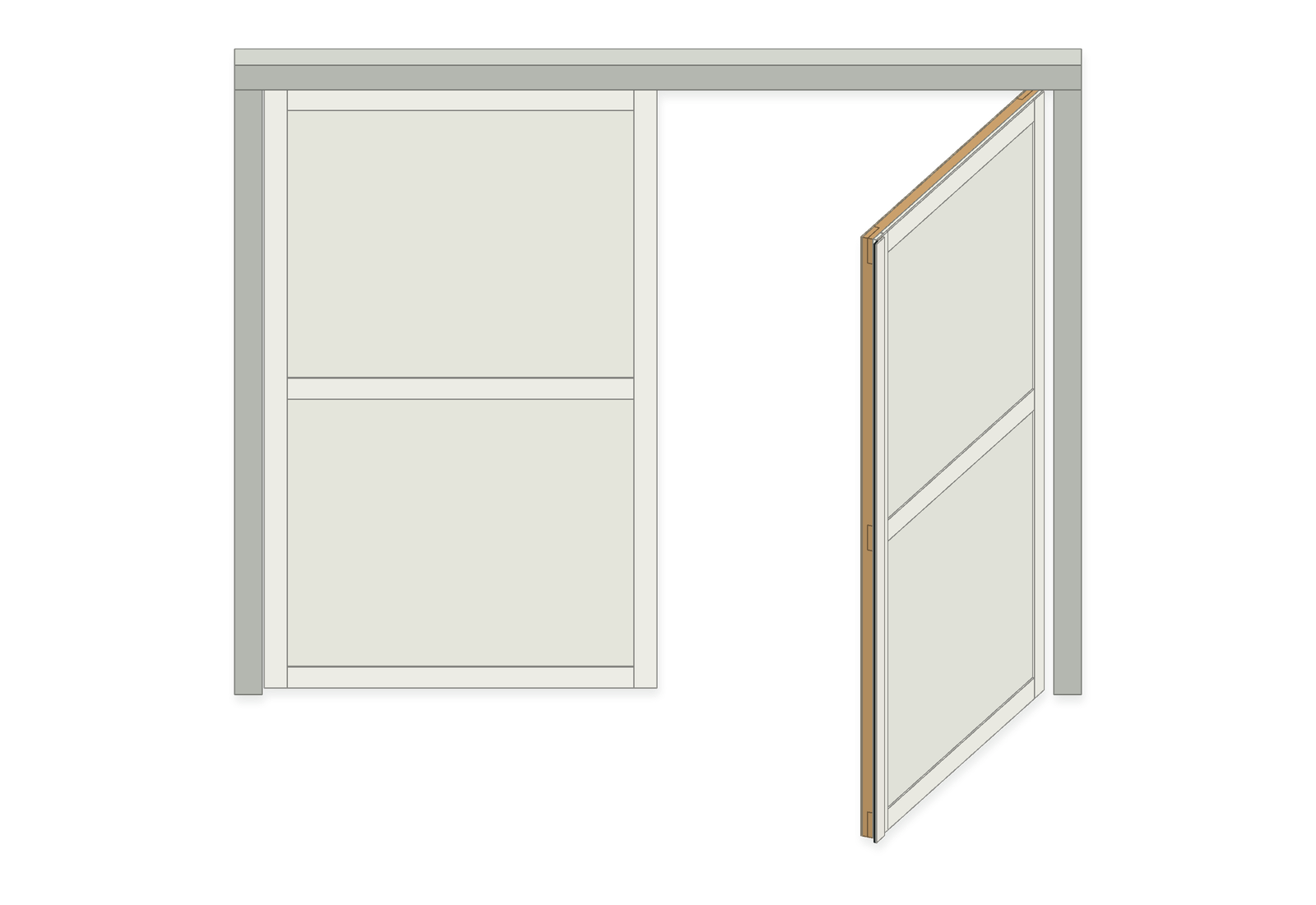
Cut the frame joints
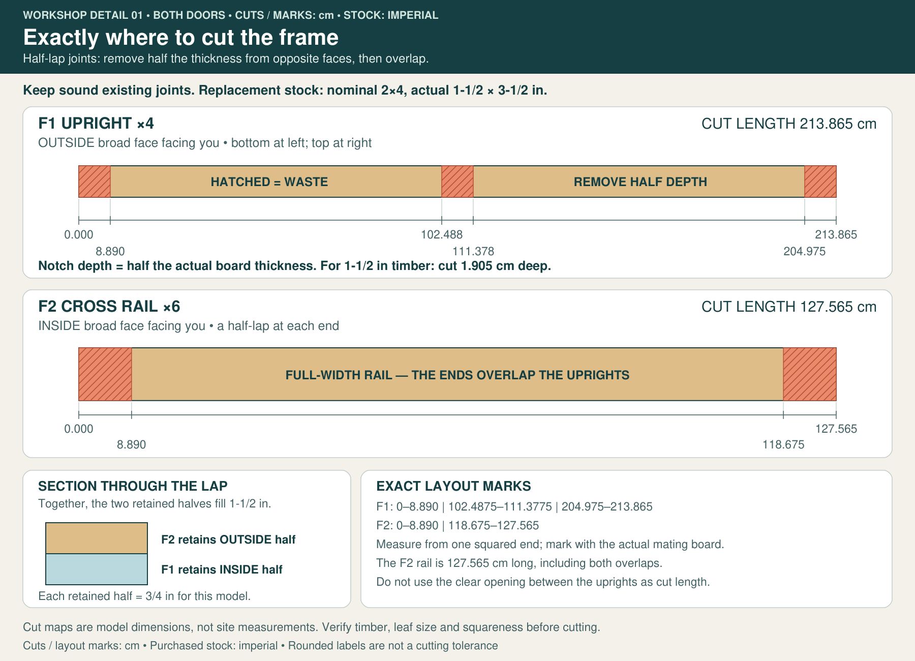
The replacement frame uses full-width rails and complementary half-laps. Remove the outside half of each upright and the inside half at both rail ends. For actual 1½ in stock, the reference lap cut is 8.89 cm long × 1.905 cm deep.
| Member | Lap positions · cm | Face to remove |
|---|---|---|
| F1 upright · cut 213.865 cm | 0–8.89; 102.4875–111.3775; 204.975–213.865 | Outside half |
| F2 rail · cut 127.565 cm | 0–8.89; 118.675–127.565 | Inside half |
Mark the waste faces
Saw, chisel and trial-fit
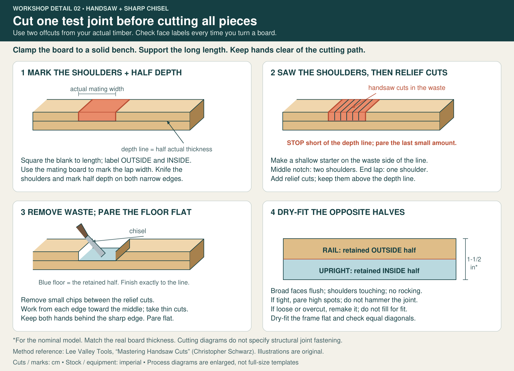
- Knife the shoulders and depth lines on both edges. Clamp the timber with the waste supported.
- Saw on the waste side of each shoulder. Add relief cuts without crossing the depth line. Remove small chips with the chisel, then pare the floor flat.
- Trial-fit until both faces are flush, the shoulders touch and the joint does not rock. Do not enlarge a loose joint with more cutting.
- Clamp the completed reference rectangle flat. Both diagonals should match; the model diagonal is 249.020 cm. Resolve the final joint connection and resistance to sag for the actual door before adding skins.
How to attach the strips
There are two different strips at the meeting edge. P2 completes the outside plywood width and fixes directly to the timber. T1 is the decorative strip over that seam. Attach P2 independently before fitting T1; P4 fixes independently on the inside.
Follow the fixing through each layer
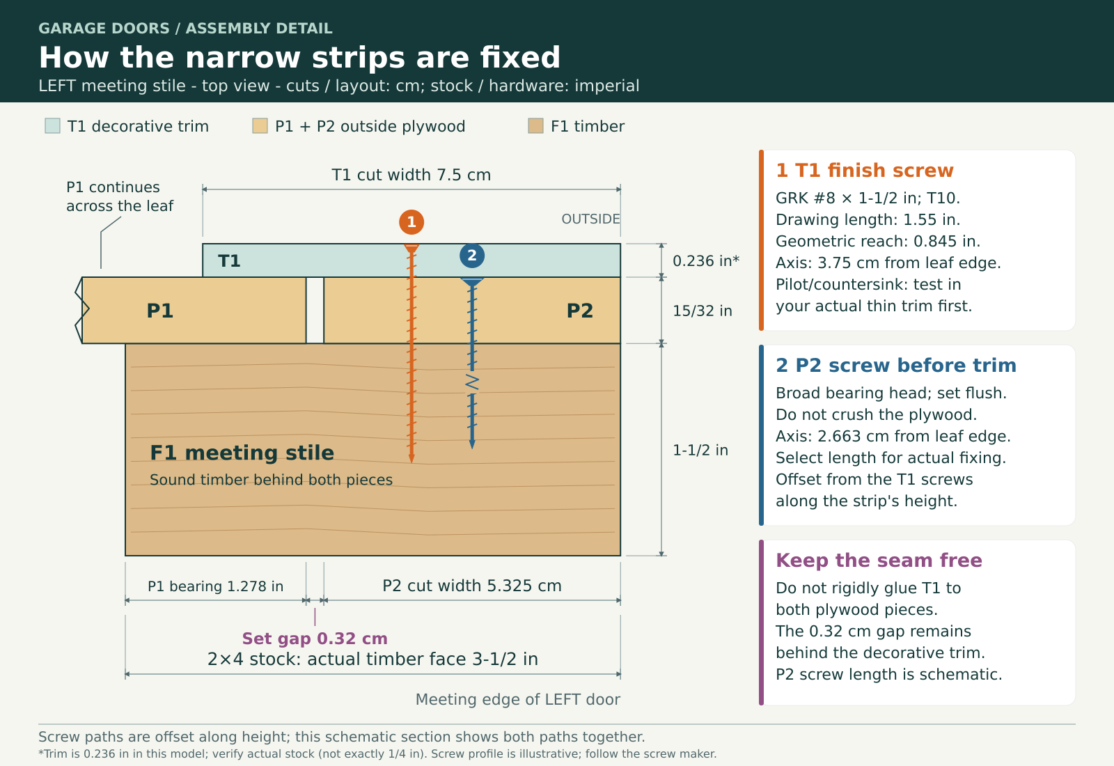
Lay out the trim screws
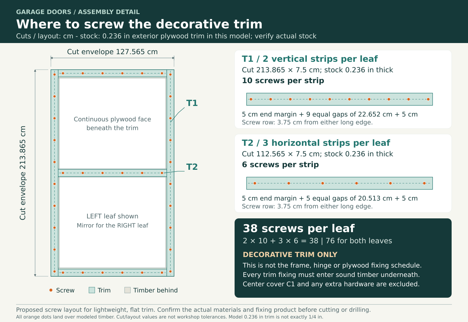
| Part | Pieces | Screws each | Position marks · cm |
|---|---|---|---|
| T1 vertical | 4 | 10 | First / last 5 from ends; spacing 22.6517; row 3.75 from long edge |
| T2 horizontal | 6 | 6 | First / last 5 from ends; spacing 20.513; row 3.75 from long edge |
- Dry-fit the full-height T1 pieces first. T2 has square 90° ends and fits between them. Transfer a common level across the closed pair so the rails align.
- For the decorative trim, the example is GRK FIN/Trim #8 × 1½ in with a T10 drive and a finish suitable for the wood and exposure. Put every screw over timber and stagger it to miss the earlier skin fixings.
- Clamp the strip. Test the actual screw in matching offcuts; select an imperial clearance bit for the strip and an appropriate smaller pilot for the timber. Drive slowly with a low clutch until flush.
- Do not pull the small trim head deeply into the thin strip. Keep the decorative trim from making a rigid bridge across the plywood movement seam.
The independent skin examples are a measured 1¼ in screw for the 15/32 in outside strip and a measured 1 in screw for the 1/5 in inside strip, with heads suitable for retaining plywood. Their length examples do not establish the structural panel fastening schedule.
A clean finish between the doors
A slim center cover hides the operating gap and compresses a gasket against the left door. The cover, spacer and gasket travel with the active right leaf.
Center cover, spacer and seal
| Part / mark | Cut or layout · cm |
|---|---|
| C1 cover | 213.865 × 6 before fitting the ends |
| C2 spacer | 213.865 × 3 before fitting the ends |
| Cover width chain | 2.4 free left overlap + 0.6 center gap + 3 right support = 6 |
| Fixing row | 1.5 inside the right meeting edge; 4.5 from the cover’s left edge |
- Choose the gasket before setting the spacer thickness. The modeled spacer is 0.118 in and the model’s compressed seal profile is 0.866 in wide × 0.118 in thick; those are examples, not a purchase specification.
- The cover example uses 10 additional GRK FIN/Trim #8 × 2 in screws into the right meeting timber. Fit the ends to the head and bottom seals, then space the fixings about 5 cm from the fitted ends and evenly between.
- Keep the cover removable for gasket service. No screw or rigid glue connection may cross into the left leaf. Mount handles and latches to suitable framing.
- Open the right first, then release and open the left. To close, close and bolt the left first; close and latch the right last.
Take it to the workshop
Keep the illustrated manual beside the workbench. The CSV preserves the model cut values, and the complete package includes the offline 3D viewer and original project files.
Sources and project assumptions
The model and drawings define this project’s proposed geometry. Manufacturer references inform panel movement, material compatibility, coating and fastener details; they do not certify the completed custom door.
Before fabrication, record the actual opening, stock dimensions, completed leaf weights in pounds, hinge models, structural fixing details and the selected seals. The reference model does not establish a wind, fire or thermal rating.